Route Processor with 64-MB RAM
Cisco 7000 Series Processor Boards
The RP contains the central processing unit (CPU), the system software, and most of the memory components that are used in Cisco 7000 series routers. The system software resides on eight electronically erasable read-only memory (EPROM) components, which are also called system ROMs or boot ROMs. Although these ROMs are replaceable, most system software upgrades are distributed on floppy disk. This enables you to download and boot from upgraded software images remotely, without having to remove the RP and replace the ROMs.
The RP is available with either 16 MB or 64 MB of dynamic random-access memory (DRAM). DRAM, which resides on four single in-line memory modules (SIMMs), is the system operating memory that stores routing tables, protocols, and network accounting applications. Support for 64 MB of DRAM (four 16-MB SIMMs) with was introduced with Software Release 9.17(8).
![]()
![]()
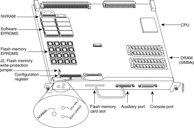
The RP, which is shown in Figure 1, is the main system processor in Cisco 7000 series routers. The RP contains the system CPU, the system software, and most of the system memory components, and it maintains and executes the management functions that control the system. The RP contains the following components:
25-megahertz (MHz) Motorola MC68040 CPU for processing key functions that
are not time-critical
| System hardware configuration register for setting default boot
instructions
| Bank of hardware (Media Access Control [MAC]-layer) addresses for the
interface ports
| Most of the memory components used by the system, including the eight
EPROM components that contain the default system software. (Although these
components actually are EPROMs, they are commonly referred to as the
software or boot ROMs.)
| If the router is running Cisco Internetworking Operating System (Cisco
IOS) Release 11.0(0), the RP contains an 8 or 16-megabyte (MB), Intel Series 2+
Flash memory card in the slot on the faceplate. (The card is optional for
other systems.)
|
|
In addition to the system software, the RP contains and executes the following management functions that control the system:
| Sending and receiving routing protocol updates
Managing tables and caches
|
Monitoring interface and environmental status
|
Providing Simple Network Management Protocol (SNMP) management and the
console/Telnet interface
|
|
Figure 1 shows the various types of memory on the RP, and Table 1 lists the functions of each type.
| Memory Type | Size | Quantity | Description | Location |
|---|---|---|---|---|
|
EPROM |
4 MB1 |
8 |
4-megabit (Mb) EPROMs |
ROM1-ROM8 |
|
DRAM |
16 MB |
4 |
4-MB SIMMs |
SIMM sockets U35, U36, U58, U59 |
|
NVRAM2 |
128 KB |
1 |
128 kilobyte (KB) |
U120 |
|
EEPROM3 |
- |
1 |
Board-specific information, address allocator |
U108 |
|
Onboard |
4 MB |
16 |
256-KB |
U14-U17, U27-U30, U45-U48, U60-63 |
|
Flash memory card4 |
8 or 16 MB |
1 |
PCMCIA Flash memory card |
Flash memory card slot on faceplate |
Cisco 7000 series routers support downloadable system software and microcode for most upgrades, which enables you to remotely download, store, and boot from a new image. ROM replacement is seldom necessary.
Eight EPROMs contain the default and bootstrap system software. ROMs for Maintenance Release 9.17(7) and later also contain the latest microcode version, in compressed form, for each interface processor. At system startup, an internal system utility scans for compatibility problems between the installed interface processor types and the bundled microcode images, then decompresses the images into running memory (RAM). The bundled microcode images then function the same as images loaded from the microcode ROMs.
DRAM stores routing tables, protocols, and network accounting applications. The standard RP configuration is 16 MB of DRAM, and an RP with 64 MB is available as an option or an upgrade.
Effective with Maintenance Release 9.17(8) and Maintenance Release 9.21(3), the following memory options are available:
| The RP in new systems is available with 16 MB of DRAM, which is the
default, or with 64 MB of DRAM (RP-64MB-OPT).
RP spares are available with the default 16 MB (RP=) or with 64 MB
(RP-64MB=) of DRAM.
|
An upgrade (RP-64MB-U) provides an RP-64MB= as a replacement for earlier
RP versions that do not support 16-MB SIMMs. The upgrade requires that you
return your existing RP to the factory and offers a significant cost savings
over the RP-64MB= spare.
|
|
If your RP supports 16-MB SIMMs, you can upgrade the DRAM from 16 MB to 64 MB. (Because 8 MB x 9 SIMMs are not available, 32 MB is not an option.) Otherwise, you must replace the entire RP to increase the amount of DRAM. To determine whether or not your RP supports 16-MB SIMMs, see the "Compatibility Requirements" section.
The system configuration, software configuration register settings, and environmental monitoring logs, are backed up with built-in lithium batteries that retain the contents for a minimum of five years. When replacing an RP, be sure to back up your configuration to a remote server so that you can retrieve it later. (See the Timesaver note that follows.)
| TimeSaver Before you replace an RP, back up the running configuration to a Trivial File Transfer Protocol (TFTP) file server so you can retrieve it later. If the configuration is not saved, the entire configuration will be lost—inside the NVRAM on the removed RP—and you will have to reenter the entire configuration manually. Refer to the "Saving and Retrieving the Configuration File" section for instructions on how to save the configuration file. This procedure is not necessary if you are temporarily removing an RP you will reinstall; lithium batteries retain the configuration in memory until you replace the RP in the system. |
The RP contains onboard Flash memory and may also contain a Flash memory card. The Flash memory card is required for downloading software images larger than 4MB (compressed). The Enterprise and the Enterprise and APPN images of Cisco IOS Release 11.0 and later will require a Flash memory card.
Flash memory allows you to remotely load and store multiple system software and microcode images. You can download a new image over the network or from a local server and then add the new image to Flash or replace the existing files. You can then boot routers either manually or automatically from any of the stored images. Flash memory also functions as a TFTP server to allow other servers to remotely boot from stored images or to copy them into their own Flash memory. For security, jumper J2, which is adjacent to the embedded Flash components (see Figure 1), provides Flash write protection. (See the "Jumpers" section that follows.)
The Flash memory card installs in the card slot on the RP faceplate. This card is an 8 or 16-MB, Intel Series 2+ Flash memory card, which conforms with the Personal Computer Memory Card International Association (PCMCIA) format. For more information, see the "Using a Flash Memory Card" section.
An EEPROM on the RP (and on the SP [or SSP] and each interface processor) stores board-specific information such as the board serial number, part number, controller type, hardware revision, and other details that are unique to each processor. In addition to this standard information, the RP EEPROM also contains an address allocator, which is a bank of 40 hardware or MAC-level addresses, one for each possible port in the system. For an explanation of the hardware addressing function refer to the "MAC Address Allocator" section.
The hardware configuration register is a 50-pin jumper block located near the left front of the processor. (See Figure 1.)
![]()
![]()
By installing jumpers on specific pins you can define system boot instructions, set broadcast addresses and console baud rates, instruct the router to perform factory diagnostics at startup, and recover from a lost password.
Jumper J2, which is located near the configuration register, provides write protection for onboard Flash memory. (See Figure 1.) The jumper is installed on J2 by default, which allows you to write to Flash memory. When the jumper is removed, Flash is read-only; you cannot write to Flash or erase the contents until you replace the jumper.
For detailed descriptions of the configuration register, the Flash protection jumper, and all system jumpers and their settings refer to the "Hardware Configuration Register" section.
Jumpers J3 and J4 are set according to the size of the eight system software EPROMs. You need to reset these jumpers only if you replace the system software EPROMs with EPROMs of a different size (capacity). Do not reset these jumpers when you download new software into Flash memory, regardless of the size of the new image.
The three LEDs on the RP indicate the system and RP status. The normal LED is on when the system is operational. During normal operation, the CPU halt and boot error LEDs on the RP should be off. When the system is turned on or restarted, the boot error LED goes on for one or two seconds, then goes off. The CPU halt LED, which goes on only if the system detects a processor hardware failure, should never be on. The Cisco 7000 model provides a redundant normal LED on the faceplate. The RP controls both LEDs and turns both on in parallel to indicate that the system is operational.
Two asynchronous serial ports on the RP, the console and auxiliary ports, allow you to connect external devices to monitor and manage the system. The console port is an Electronics Industries Association/Telecommunications Industry Association (EIA/TIA)-232 receptacle that provides a data circuit-terminating equipment (DCE) interface for connecting a console terminal. (Prior to the acceptance of the EIA/TIA standard by the ANSI committee, it was referred to as a recommended standard called RS-232.) The auxiliary port is an EIA/TIA-232 plug that provides a data terminal equipment (DTE) interface; the auxiliary port supports flow control and is often used to connect a modem, a channel service unit (CSU), or other optional equipment for Telnet management.
All local-area network (LAN) connections (ports) require a unique MAC-layer address, which is also known as a physical or hardware address. Typically, the MAC address of an interface is stored on a component that resides directly on the interface circuitry, as it does on earlier Cisco router platforms (for example, on individual appliques). Every interface on the earlier platforms contains a programmable read-only memory (PROM) component with that interface's unique MAC address. The router system code reads the PROM for each interface in the system, learns the MAC addresses, and can then initialize appropriate hardware and data structures.
The Cisco 7000 series, however, requires a different method of handling the MAC addresses because of the online insertion and removal (OIR) feature. OIR allows you to remove an interface processor and replace it with another identically-configured one. If the new interfaces match the current configuration (that of the interfaces you removed), the system immediately brings them on line.
In order to allow OIR, an address allocator with 40 unique MAC addresses is stored in an EEPROM on the RP. (Because the RP supports both the seven-slot and five-slot platforms, the address bank must contain addresses for the maximum possible configuration: 40 possible interfaces [5 interface processor slots x 8 ports] in the seven-slot model. The five-slot model uses only the first 24 addresses [3 interface processor slots x 8 ports] in the MAC allocator.) Each address is assigned to a specific slot/port in the router regardless of whether or not an interface resides in that port. The MAC addresses are assigned to the ports in sequence; the first address is assigned to port 0/0, the 20th to port 2/4, and the last (40th) to port 4/8. This address scheme allows you to remove interface processors and insert them into other chassis without causing the MAC addresses to move around the network or be assigned to multiple devices.
Note that if the MAC addresses were stored on each interface processor, OIR would not function because you could never replace one interface with an identically configured one; the MAC addresses would always be different. Also, each time an interface was replaced, other devices on the network would have to update their data structures with the new address and, if they did not do so quickly enough, could cause the same MAC address to appear in more than one device at the same time. Storing the MAC addresses on the RP avoids these problems. When an interface is replaced with another interface with the same configuration, there is no need for other devices in the network to update their data structures and routing tables.
Storing the MAC addresses for every port in one central location on the RP also means that the MAC addresses stay with the RP on which they are stored. If you replace the RP, the addresses of all ports will change to those specified in the address allocator on the new RP. Because the system configuration is also stored on the RP (in NVRAM) and also stays with the RP when you remove it, you will need to reenter the configuration if you replace the RP.
FOR MORE INFORMATION
http://www.cisco.com/univercd/cc/td/doc/product/core/cis7000/40164